After the success of the DoT project project, which used an ESP8266 to notify me when someone rings my doorbell, wherever I am, I have finally finished work on my second ESP8266 project. This project is a simple device that reads data from a solar power inverter and sends them to a local web server for logging.
Going Solar
Like many people, I have taken the first steps to not being an environmental vandal by installing some solar panels on my roof. The solar panels are connected to a Delta Solivia 3.3TR inverter, which converts the DC input from the solar panels to 240V AC to power my house or feed power to the grid if we’re generating more than we’re using.
The inverter has a 16x2 display on it, on which it displays the current AC power that is being generated (i.e. after the losses inside the inverter). This is very interesting information to know, and I thought it would be interesting to log it, too, so that I could see how it changes over time. At this point, the Delta Reader project was born.
RS-485
Fortunately, the Delta inverter itself has two RS-485 ports available for communications. RS-485 is a serial interface that is used in many devices and industrial applications, and allows for multiple (> 2) devices to communicate over a single pair of wires. In this application, I am only using my device to talk to the inverter.
Both of the physical RS-485 connections are via RJ-45 connectors - the same that is used in standard Ethernet cables. Only pins 2 and 3 are used for the connections. RS-485’s wire pairs use a differential signal method, instead of a ground and logic level signal like TTL. This means that only the difference in voltage potential between the two wires is used when determining if a value is 0 or 1. Differential signals are excellent for rejecting induced noise, and allow greater communication speeds and distances with a higher reliability.
While RS-485 allows for high speed communications (up to 35 Mbit/s, according to Wikipedia), the communications for the inverter is fixed at 19,200 bps. While that speed may be slow by modern communications standards, even the longest packet response for this application at 13 bytes would only take 5.42ms.
Getting an ESP8266 to Talk RS-485
As I wrote in my post Quiet, UART!, the ESP8266 has one and a half UARTs, which can send and perhaps receive serial data. These UARTs only send a logical signal (0V = 0, 3.3V = 1), rather than conforming to either RS-232 (used in pre-USB PC serial communications) or RS-485. Just like how a chip like the FTDI FT232RL is required to allow the ESP8266 to talk to a PC via USB, a MAX485 chip is used to talk over RS-485. I used a pre-built breakout that included the MAX485, as well as required resistors/capactors that I bought off AliExpress - similar to these.
The MAX485 chip is a half-duplex communications chip, which means that it can be either sending or receiving data, but not both at the same time. Another pin from the ESP8266 is used to instruct the MAX485 as to the direction of communications. If this is set wrong, data will be lost.
Communications Format
What RS-485 does not specify is what data should be transmitted over the serial link. I managed to find (and subsequently lose) some documentation on the Internet as to what the communications packet structure looks like, and what commands are accepted by the inverter. All communications with the inverter are based on a simple request/response pattern, with whatever device (ESP8266, PC, or something else) sending a request packet to the inverter, with the inverter then sending a response packet back in return. The inverter will never send an unsolicited message.
The packets that are sent utilise the following structure:
| Byte(s) | Symbol | Hexadecimal | Description |
|---|---|---|---|
| 1 | STX | 0x02 | Start of TeXt |
| 2 | ADDR | 0x05 / 0x06 | Address of recipient (0x05 = inverter, 0x06 = reader) |
| 3 | ID | 0x01 | Chain ID of the inverter |
| 4 | LEN | N/A | Length of the command (including any response data) |
| 5..6 | Command | N/A | The command that is being requested or responded to |
| 7..(4 + LEN) | Data | N/A | The data for the command response (if any) |
| (5 + LEN)..(6 + LEN) | CRC | N/A | CRC-16 of packet contents |
| (7 + LEN) | ETX | 0x03 | End of TeXt - the last byte in the packet |
The key data for each request/response is the command. This is a series of two bytes, representing a single piece of information for the inverter. The response for numeric values will always be of the same length for a given command, making parsing the response very simple.
Note that while there is an ETX character to mark the end of the packet, there is no byte stuffing to ensure that no other ETX character appears without an escape prefix, so simply searching for the first 0x03 byte will not necessarily find the end of the packet.
Chosen Commands
With this information, I was able to plan what to get from the inverter. In the end I chose the following data points:
| Byte 1 | Byte 2 | Tag Name | Data |
|---|---|---|---|
| 0x10 | 0x01 | instant-current-i1 | Instantaneous current - Input 1 |
| 0x10 | 0x02 | instant-voltage-i1 | Instantaneous voltage - Input 1 |
| 0x10 | 0x03 | instant-power-i1 | Instantaneous power - Input 1 |
| 0x11 | 0x01 | average-current-i1 | Average current - Input 1 |
| 0x11 | 0x02 | average-voltage-i1 | Average voltage - Input 1 |
| 0x11 | 0x03 | average-power-i1 | Average power - Input 1 |
| 0x20 | 0x05 | internal-temp-ac | Internal temperature - AC assembly |
| 0x21 | 0x08 | internal-temp-dc | Internal temperature - DC assembly |
| 0x10 | 0x07 | instant-current-ac | Instantaneous current - AC output |
| 0x10 | 0x08 | instant-voltage-ac | Instantaneous voltage - AC output |
| 0x10 | 0x09 | instant-power-ac | Instantaneous power - AC output |
| 0x10 | 0x0A | instant-frequency-ac | Instantaneous frequency - AC output |
| 0x11 | 0x07 | average-current-ac | Average current - AC output |
| 0x11 | 0x08 | average-voltage-ac | Average voltage - AC output |
| 0x11 | 0x09 | average-power-ac | Average power - AC output |
| 0x11 | 0x0A | average-frequency-ac | Average frequency - AC output |
| 0x13 | 0x03 | day-energy | Day energy |
| 0x13 | 0x04 | day-run-time | Day running time |
| 0x14 | 0x03 | week-energy | Week energy |
| 0x14 | 0x04 | week-run-time | Week running time |
| 0x15 | 0x03 | month-energy | Month energy |
| 0x15 | 0x04 | month-run-time | Month running time |
| 0x16 | 0x03 | year-energy | Year energy |
| 0x16 | 0x04 | year-run-time | Year running time |
| 0x17 | 0x03 | total-energy | Total energy |
| 0x17 | 0x04 | total-run-time | Total running time |
| 0x12 | 0x01 | solar-current-limit | Solar current limit - Input 1 |
| 0x12 | 0x02 | solar-voltage-limit | Solar voltage limit - Input 1 |
| 0x12 | 0x03 | solar-power-limit | Solar power limit - Input 1 |
| 0x12 | 0x07 | current-max-ac | AC current max |
| 0x12 | 0x08 | voltage-min-ac | AC voltage min |
| 0x12 | 0x09 | voltage-max-ac | AC voltage max |
| 0x12 | 0x0A | power-ac | AC power |
The descriptions are the best I have been able to come up with, as the original documentation that I could find was an Excel spreadsheet in German, which is not a language I speak - so liberal use of Google Translate and educated guessing was used to come up with what I hope are relatively accurate values.
Tag Names?
Those who looked closely at the above table will have noticed a column called “Tag Name”. This relates to how I am processing the data on the server side. The values for each command are stored in a real-time tag database, where only the latest value for that tag are kept. Other code on the server then reads these tag values from the database and stores them into an SQL database for future analysis. These two databases are shared among other programs and projects communicating with the server, this work of mine dates back almost ten years now.
The tags themselves must be unique across the entire tag database to avoid overwriting values from either within the inverter’s fields, or between the inverter and other logged values.
Sending the Data to the Server
The ESP8266’s program reads each of the above values from the inverter, one at a time, then sends a single HTTP POST request to the server, with the tag names and their values encoded in a JSON structure. JSON is a nice format for this, as it is easily parsed on the web server, and relatively light weight (compare it to XML), so it’s also easy to create on the ESP8266.
Unfortunately, JSON is a text format, which means that a large amount of data needs to be pieced together for transmission. While it is possible to stream this data out via TCP/IP as it is being assembled (e.g. one tag at a time), there is enough RAM in the ESP8266 to be able to piece the entire structure together and send it in one go.
The problem with text is that while we know how many numbers we want to send, and how many bytes they hold in a binary representation, the number of bytes they will require when converted to text is unknown. For an example, the number 0x00 is one character of text (“0”), while 0x0A is two (“10”) and 0xFF is three (“255”). So a single 8-bit number can take anywhere from 1-3 characters. The problem gets worse for 16-bit (1-5) and 32-bit (1-10) numbers.
To make matters worse, we need to put a line in the HTTP header (i.e. before we start sending the values) containing the number of bytes in the message body. To cope with the varying lengths, we have to either create the whole structure in memory (what I’m doing) or make two passes over the values, converting them to decimal and throwing it away the first time, just to count how many bytes will be required, and then converting them a second time when actually sending the values.
Another language that I program in (not in ESP8266s) is Java, and it has a class in it’s base library called a StringBuilder. This class holds an internal character array which is resized as needed whenever it overflows. I created a similar set-up in C, without the fancy OO encapsulation, which allows me to build the HTTP request string and only send it when I’m ready, as well as to query the created string as to it’s length when constructing the HTTP header.
The actual sending of the HTTP packet is very easy. Set up a TCP/IP connection in the normal way for an ESP8266, and then make a single call to espconn_send.
Serial Problems
While working through the code, I had a lot of problems reading the serial responses from the inverter. After a lot of investigations, I worked out that the ESP8266 was lying to me. My serial transmissions were made using the uart_tx_one_char function, which I thought was synchronous, as there is also a uart_tx_one_char_no_wait function. Unfortunately, it is not synchronous, so the direction pin in the MAX485 was being set to receive while the ESP8266 was still transmitting, which truncated the messages. Adding a 5ms delay after the transmission request before clearing the output fixed the issue. Later testing with an oscilloscope (that I bought after already solving this particular problem) showed that this gave me a 600 microsecond buffer between the transmission of the last character and the setting of the direction pin.
While trying to work out why things weren’t working correctly, I tried a new approach with the serial connections. I decided to not use a call-back for when serial data arrives. Instead, I set up a 5ms timer, and check at each expiry if we have received enough data yet. This timer was also then used for a time-out - if we try too many times, we simply assume that the inverter is not going to reply at all. This occurs every night - once there is insufficient power coming from the solar panels to drive the inverter, it switches itself off.
Program Flow
The basic program flow is as follows:
- Initialise the ESP8266, and start a 1 minute timer
- At the expiry of the timer send the first command request to the inverter
- Poll every 5ms for a reply from the inverter. Once we have response, validate the packet, store the value and transmit the next command request.
- Once all command requests have been correctly replied to, form the HTTP request.
- Connect to the server.
- Once the connection is established, send the HTTP POST request.
- Parse any HTTP reply for success/failure.
If you look closely at the program, you’ll see that there isn’t a single, overarching loop that is run through for each group of transmissions. This is due to the call-back nature of ESP8266 programming (even when using a timer instead of a serial call-back), and because it could take too long to do it all in one big go. The recommendation is that no task should take longer than 2ms, and the watchdog will reset the ESP8266 if control isn’t returned to the underlying system in 500ms.
The Delta Reader Circuit
The Delta Reader circuit is another simple one, electrically speaking. There is a 5V power supply (the MAX485 requires 5V) from an old USB phone charger whose connector got smashed, a 5V->3.3V converter for the ESP8266 and the MAX485 and ESP8266 devices themselves. Throw in a few resistors to keep the ESP8266 happy, and three wires between the ESP8266 and the MAX485 and that’s it!
After much debate around the internet, it was finally confirmed that the GPIO inputs on the ESP8266 are 5V tolerant, so I didn’t bother to add any level shifting for the MAX485->ESP8266 connection.
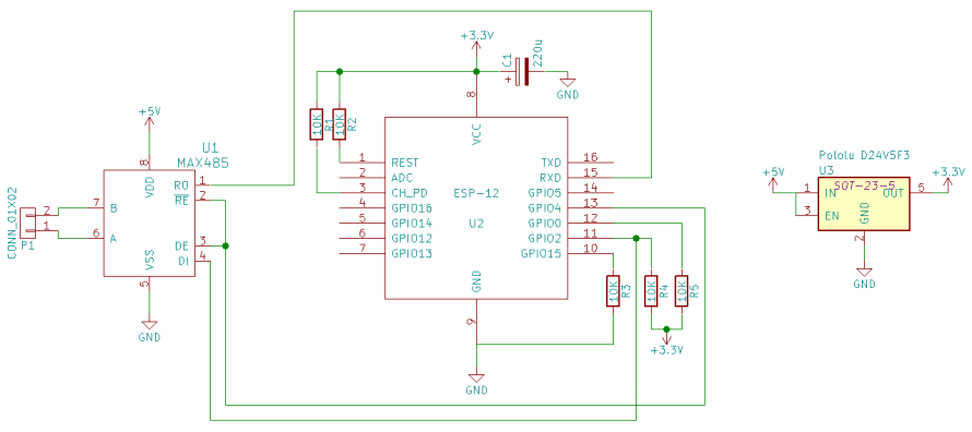
Note that like the schematic for DoT, I use a different step-down voltage regulator than in the above schematic. It’s just what was available in the default KiCad component libraries, and I couldn’t find a compatible one for the Pololu D24V5F3 unit I used.
The Program
The program for the Delta Reader has been placed in my normal place in GitHub, alongside all of the demonstration projects. It builds on the make files, remote debugging and OTA upgrade code that I have introduced in earlier blog posts. The full source code is available here.