Today I am writing about my first actual project based on an ESP8266 microcontroller. It has taken quite a bit more effort to prepare than I’d first thought, hence the larger than average delay between the last post and this one. This project started out as a silly idea, that somehow became serious. This project is called “DoT”, short for “Doorbell of Things”. This is a tongue in cheek reference to the “Internet of Things” (IoT) craze that is sweeping buzzword bingo across the world. IoT involves putting electronics into everyday objects (things) that can communicate across the internet somehow.
We recently bought a new doorbell to replace our old, dodgy one. A doorbell that doesn’t ring is actually worse than useless - people thought that they were ringing the bell, but we didn’t hear a thing. The old doorbell was a typical (read cheap) wireless doorbell model from a known, but not spectacular consumer brand bought from the local hardware store. To replace it, I decided that I wanted a wired doorbell, to ensure that if the button is pressed, that the doorbell will chime. The only wired unit available at the local hardware store was a mechanical doorbell, with a solenoid that drives a central pin to ring the two chimes on either side of the doorbell:
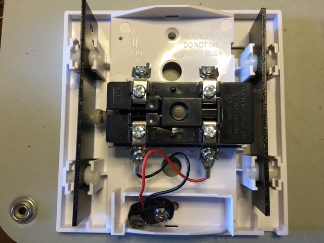
With the space available at the top of the unit, I realised that I could squeeze an ESP8266 in there, and send through notifications when the doorbell is pressed. By sending messages over the internet, I can receive doorbell notifications on my phone, as well as PC, even when I’m not at home. The question as to how to get the notifications to my phone, as well as my wife’s was a thorny one - I didn’t really want to go and write a new application for our phones just to get the notifications.
Notification Service
Initially, SMS was going to be the answer, but I couldn’t find a good free site for sending SMS messages via an HTTP call. I did find that I can use IFTT with the “Maker” channel and the “SMS” channel working together to send messages. While that did work, it unfortunately took quite a while for the message to actually arrive at my mobile, which kind of defeated the point of getting a notification that someone was at my door! After some looking around, I settled on the Pushbullet web site, which allows for a notification to be sent to a channel, which is then pushed to all receivers. The pushes from the notifications are received quickly, and can be received by multiple people and devices simultaneously. This is nice, as it means that the ESP8266 only has to make a single request, while multiple recipients receive the message.
Pushbullet provides a nice API that can be used to interact with the service. To post a message, only a single API, called “pushes” is necessary. Sending messages via the Pushbullet API requires an API token, which can be retrieved for free from Pushbullet account settings. All calls to the Pushbullet API must be made via an encrypted (HTTPS) connection.
Intercepting The Doorbell Press
The circuit for the original doorbell is trivially simple, a 12V AC power supply is connected through the doorbell button, and then across the solenoid. When the button is pressed, the 12V is applied across the solenoid, pushing the pin to strike one of the chimes. When the button is released, the solenoid is somehow being drawn in the opposite direction to strike the second chime, making the pleasing “ding dong” sound. I’m guessing that there must be something to do with the collapsing of the field in the inductor pushing the pin the other way, but I don’t know for sure.
My first plan was to have the doorbell button trigger the ESP8266 and the doorbell simultaneously, but ran aground of issues of things like AC vs DC. This called for a relay, where the button would trigger the relay, which would then have separate contacts for the doorbell and the ESP8266. This has the advantage of separating the electronics and code in DoT and the triggering of the doorbell. If the ESP8266 blows up, or my code has a deadlock that makes it lock up, the doorbell will still ring. Fail-safety is a key requirement, as it’s not a big deal if the Pushbullet notification fails, but it is if the doorbell doesn’t ring.
Unexpected Failure
The original circuit and associated code was breadboarded up, and worked correctly. Except on the occasion that it didn’t. There was nothing in there that I could see as to why the call to the internet was failing sometimes, but not others. After a lot of investigations, I stumbled on the answer sort of by chance. Whenever I had the ESP8266 too close to the doorbell, it tended to fail, whereas it tended to work if I had it a little further away. My best theory on this is the solenoid in the doorbell spewing out EM radiation when it is activated, and more importantly deactivated, which interferes with the ESP8266 - via the on-board antenna, perhaps?
Looking at the logs that were coming out of the ESP8266, it would get part way through the communications with the Pushbullet server, then suddenly reset, on a reset pin being activated. I do know that the reset pin was not being changed, as it was tied up to VCC via a 10K resistor, so I’m guessing that it must just be interference somehow confusing the ESP8266.
This failure forced me to abandon the placement of the ESP8266 inside the housing of the doorbell, which would have been simpler and aesthetically pleasing. The plan is now to have the DoT circuitry far away from the doorbell, roughly half way between the front button and the doorbell unit itself. Why so far, when only 10cm would have been enough to make it work? Because that’s where there is a nice place where I can hide the ESP8266 out of sight, with easy access to cables and the unit itself, should I have a need to fix anything that goes wrong without having to climb into the roof space.
The DoT Circuit
By forcing the DoT unit to be separated from the doorbell, I had to put a second power supply to the DoT unit. This is a 12V power supply from an old (and no longer working) Apple Airport. This supply has the capacity to supply far more power than the circuit needs, which is a bit of a waste, but it was already paid for, and supplied a very nice, stable 12V of power. A spare-parts box that contains as many power supplies as possible is a definite plus. This drives a 12V relay with DPDT (double pole, double throw) contacts, as well as a 12V - 3.3V step-down converter to power the ESP8266. A step-down converter is a very useful component to use for such a solution, as it is far more efficient than the more normal linear regulators.
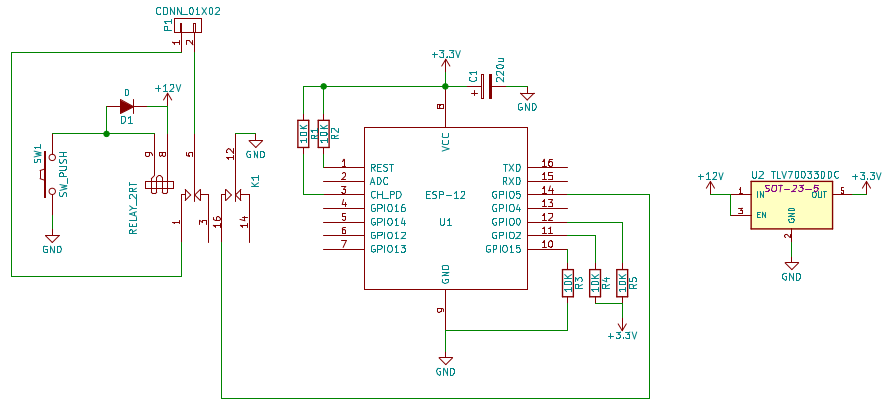
Note that in the above schematic, I use a different step-down voltage regulator. It’s just what was available in the default KiCad component libraries, and I couldn’t find a compatible one for the Pololu D24V5F3 unit I used.
How The Code Works
Like so many other electronics projects that contain a microcontroller, the bulk of the complexity is contained within the code running on the ESP8266, but even then, it’s rather simple. Most of the time, the ESP8266 does absolutely nothing - it’s waiting for the button to be pressed.
Noticing The Button Has Been Pressed
To check for the button to be pressed, there are two options:
- Polling - repeatedly checking to see if the button has been pressed
- Inerrupts - getting the ESP8266 to invoke a function when the button has been pressed
Polling is simpler, conceptually, just keep looping around to see if the button has been pressed. This unfortunately has the effect of using more power to operate (as it’s running full-tilt to see if the button’s been pressed), as well as there being the possibility of missing a button press if the press occurs between two checks for the state. While this is unlikely in the advent of a human pressing a button and a microcontroller checking it every few microseconds, it is still a possibility.
The better answer is to utilise an interrupt. The ESP8266 has hardware in-built to generate an interrupt whenever a set condition arises on one of the GPIO pins. In this case, I’ve set up the ESP8266 to look for a negative edge on GPIO 5. There are five different conditions that may be checked for on a GPIO pin:
- Positive edge - the transition from 0 to 1
- Negative edge - the transition from 1 to 0
- Any edge - the transition from 0 to 1 or from 1 to 0
- Low level - any time the GPIO pin is 0
- High level - any time the GPIO pin is 1
So the negative edge interrupt will trigger my function when the pressing of the button pulls the GPIO pin from 1 to 0. This is set up via the following code:
1
2
3
4
ETS_GPIO_INTR_DISABLE();
gpio_intr_handler_register(gpio_interrupt, NULL);
gpio_pin_intr_state_set(GPIO_ID_PIN(5), GPIO_PIN_INTR_NEGEDGE);
ETS_GPIO_INTR_ENABLE();
The gpio_interrupt function is as follows:
1
2
3
4
5
6
7
8
9
10
11
12
13
14
15
16
17
LOCAL void gpio_interrupt(uint32_t intr_mask, void *arg) {
    // Get the interrupt information.
    uint32_t gpio_status = GPIO_REG_READ(GPIO_STATUS_ADDRESS);
    gpio_intr_ack(intr_mask);
    os_printf("GPIO interrupt - %04x, %04x.\n", intr_mask, gpio_status);

    // Notify Pushbullet, if we're not already.
    if (!pb_in_progress) {
        pb_in_progress = true;
        espconn_gethostbyname(&pb_conn, PB_HOSTNAME, &pb_ip, have_pb_ip);
    } else {
        os_printf("Not sending to pushbullet, as call is currently in progress.\n");
    }

    // Re-assert the interrupt for this pin.
    gpio_pin_intr_state_set(GPIO_ID_PIN(5), GPIO_PIN_INTR_NEGEDGE);
}
It took some Googling and playing around to find out how to make the interrupts work more than once, and it involved the reading of the GPIO_STATUS_ADDRESS register and use of gpio_intr_ack at the beginning, and the re-asserting of the interrupt at the end via gpio_pin_intr_state_set. Do things in the wrong place, or skip anything, and it simply doesn’t keep working with no error / warning messages - you have been warned!
Calling the Pushbullet API
If you look closely, the process for calling the Pushbullet API is kicked off in the gpio_interrupt function above. The following steps are required:
- Getting the IP address of the Pushbullet server from the DNS name
- Establishing a secure TCP connection to the Pushbullet server
- Sending the HTTP POST information, including the JSON payload to the Pushbullet server
- Handling the HTTP response from the Pushbullet server
Getting the IP address is performed by the espconn_gethostbyname function shown above. In that call, the have_pb_ip function will be invoked when we get the IP address, or failed trying. To establish the secure connection, the function espconn_secure_connect is invoked. Initially, this call was failing for me, until I allocated more memory to the secure connection functions in the ESP8266. I believe that this is something to do with the size of the certificates that it’s having to use for the encrypted connection. The following code snippet shows how the connection is established:
1
2
3
4
5
6
7
8
9
10
11
12
13
14
15
// Set up the connection structure for the Pushbullet API web server.
conn->type = ESPCONN_TCP;
conn->state = ESPCONN_NONE;
conn->proto.tcp = &pb_proto;
conn->proto.tcp->remote_port = 443;
os_memcpy(conn->proto.tcp->remote_ip, &addr->addr, 4);

// Connect to the Pushbullet API web server.
espconn_regist_connectcb(conn, pb_connect_cb);
espconn_regist_disconcb(conn, pb_disc_cb);
espconn_regist_reconcb(conn, pb_recon_cb);

os_printf("Connecting to %d.%d.%d.%d:%d.\n", IP2STR(&addr->addr), conn->proto.tcp->remote_port);
espconn_secure_set_size(0x01, 6144);
int8_t res = espconn_secure_connect(conn);
Sending of the information is performed through the espconn_secure_send function, which simply takes an array of bytes to be sent, and the number of bytes in the array to be sent. Note that you have to follow the HTTP communications protocol properly to be able to make your call work. I did all this by having my call be pre-defined, and simply shoving the same array of bytes down to the server each time. Note that in the below line, I’ve blanked out my token and channel to keep private things private.
1
2
3
4
#define PB_REQUEST "POST https://api.pushbullet.com/v2/pushes HTTP/1.0\r\n" \
    "Access-Token: xxxxxxxxxxxxxxxxxxxxxxxxxxxxxxxxxx\r\nContent-Type: application/json\r\nContent-Length: 88\r\n\r\n" \
    "{\"channel_tag\":\"xxxx\",\"type\":\"note\",\"title\":\"Doorbell\",\"body\":\"Doorbell has been rung.\"}"
#define PB_REQUEST_LEN 247
To help understand what this means, I’ve reproduced the values that are sent via HTTPS below - you can see that this is a standard basic HTTP header, with a short JSON string as the contents.
1
2
3
4
5
6
HTTP/1.0
Access-Token: xxxxxxxxxxxxxxxxxxxxxxxxxxxxxxxxxx
Content-Type: application/json
Content-Length: 88

{"channel_tag":"xxxx","type":"note","title":"Doorbell","body":"Doorbell has been rung."}
Sending data via the HTTPS connection is exactly the same as for a normal TCP connection (e.g. HTTP), except that the espconn_secure_send function is used, in place of the espconn_send function:
1
2
// Send through the Pushbullet request.
int8_t res = espconn_secure_send(conn, PB_REQUEST, PB_REQUEST_LEN);
Parsing the results was an interesting problem, too. After making some API calls myself through the curl program, I felt comfortable enough to see that all I really needed was the first line of the response. This contains a string like “HTTP/1.0 200 OK”. The 200 is the status code, where 200 is a success, and anything else is considered a failure. I know that there are other possible 200 range codes, but I never came across them, so I’ve left them off for now. It isn’t of major concern, as the only thing I do is to print out a debug if we don’t get a 200 reply - the doobell has been rung, and we’ve tried to call the Pushbullet service in any case, so there’s nothing more to do.
The very simple parsing code that I used was:
1
2
3
4
5
6
7
8
9
10
11
12
13
14
15
16
17
18
19
20
21
22
23
24
25
26
27
28
29
LOCAL void ICACHE_FLASH_ATTR pb_response_cb(void *arg, char *data, uint16_t len) {
    struct espconn *conn = (struct espconn *)arg;

    // Make sure the reply starts with "HTTP/1.? "
    if ((data[0] != 'H') ||(data[1] != 'T') ||(data[2] != 'T') || (data[3] != 'P') || (data[4] != '/') ||
            (data[5] != '1') || (data[6] != '.') || (data[8] != ' ')) {

    }

    // Get the status code from the response.
    uint16_t status = 0;
    for (uint16_t ii = 9; ii < len; ii++) {
        if ((data[ii] >= '0') && (data[ii] <= '9')) {
            // This is a digit, update the status code.
            status = (status * 10) + (data[ii] - '0');
        } else {
            // Stop at the first non-digit.
            break;
        }
    }

    if (status != 200) {
        // There was a problem.
        os_printf("Error returned from Pushbullet: \"%s\".\n", data);
    }

    // Close the connection ASAP, now we're done with it.
    system_os_post(PB_DISCONNECT_PRI, 0, 0);
}
Physical Setup
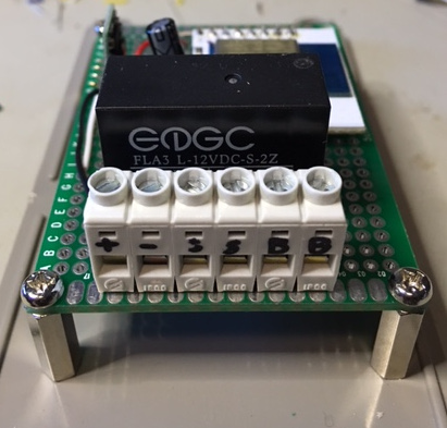
The DoT circuit was created on a simple prototyping “perf board”. I managed to fit all of the components on nice and neatly together, and mount them inside a simple ABS “jiffy” box from my local Altronics shop. Some pictures are below:
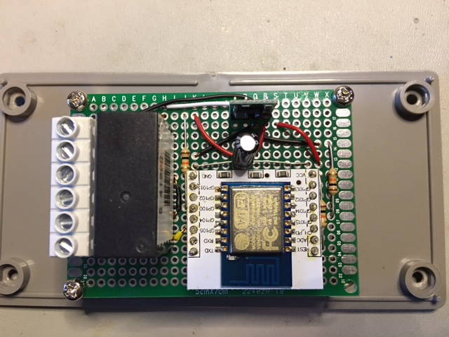
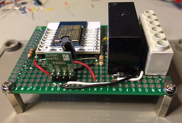
You may have noticed that there are no photos of the soldering underneath. This is not a mistake - I am still not as proficient at using my soldering iron as I’d like, and always have trouble making my perf boards look neat. The internet never forgets - and that includes bad soldering pictures!
The Program
The program for DoT has been placed in the normal place in GitHub, alongside all of the demonstration projects. It builds on the make files, remote debugging and OTA upgrade code that I have introduced in earlier blog posts. The full source code is availabe here.