So far, all of my ESP8266 projects have simply been pushing bits to various locations. This is great, but not all you can do with a microcontroller. Microcontrollers also give you the ability to make things move by controlling motors. There are lots of different types of motors that can be used to make something move, and they each have different pros and cons.
Servo motors
In this post, I am writing about servo motors. These are some of the simplest motors to control for a microcontroller, as they do most of the work for you. A servo motor consists of several components all in one motor:
- The motor itself
- Reduction gears
- Positional feedback
It is the feedback that makes the servo motor so appealing. Unlike a typical motor, a servo doesn’t spin all the way around when voltage is applied. Instead, a signal is sent to a servo motor that tells it the angle that it is desired to be at - these angles are usually between -90° and 90°. The servo uses it’s positional feedback to determine how far from the set point it is, and turns the motor to correct any errors. As this correction is applied in the servo motor, the microcontroller doesn’t have to worry about it.
The feedback nature of the motor makes things interesting - technically, it is a closed-loop control system, as the feedback is used to correct any errors in position. This would imply that sending the desired angle will always be enough, and that the servo can be trusted to control the position correctly. But what if the motor can’t reach the requested position? If there is a mechanical issue like a something blocking the motor from turning, then the servo will not be at the angle, and the microcontroller will not know about it, which suggests that it is an open-loop control system, from the microcontroller’s point of view.
Most typical low end or hobbyist servo motors use a timing based signal to set the desired angle. I will not cover higher end or industrial servos in this article, as I’ve never used one myself. Such servo motors are often used in remote control applications e.g. steering in a RC car, rudder in a RC yacht, flaps in an RC plane. Higher end devices can also use timing signals, or a true digital connection.
Servo motors have three wires that require connection, VCC, ground and signal. VCC and ground simply go to the positive and negative outputs on your supply (if they’re at the correct voltage, of course). The signal connection is a timed output, whose value is digital at either high (VCC) or low (ground). This timing signal is a sub-set of what is called pulse width modulation.
Pulse width modulation
Pulse Width Modulation (PWM) is a type of digital signal, where the value is encoded in the proportion of time that the output is high, called the duty cycle of the signal. The duty cycle of a PWM signal is typically represented as the percentage of time that the level is high versus the time that it is low. The output, therefore, can range between full low (0% duty cycle) to full logic high (100% duty cycle).
The second key parameter in a PWM signal is fixed for each application (where the duty cycle varies based on the encoded value) is the period of the signal. A PWM signal is periodic in that the output is pulsed high/low in a repeating interval. The period varies greatly between implementation, it can be anything from seconds to microseconds. By convention, PWM signals (for a duty cycle of greater than 0%) will be high at the start of the period, then turn off once the appropriate amount of time has passed, and will remain off for the rest of the period. The inverse of the period is the frequency of the PWM signal, which defines the rate at which the recipient will receive the encoded value.
PWM signals are used in many applications, including controlling power supplies, dimming lights, rough conversions of digital to analogue values (with a capacitor and/or inductor), and of course, motor control. While PWM is critical for defining the set-point for a servo motor, many non-servo motors are fed a PWM signal to control the speed of the motor’s rotation.
Controlling a servo motor from an ESP8266
Where a PWM signal can have a value that ranges from 0% to 100%, typical hobbyist servo motors operate in a very narrow set of values. The period of these motors is 20ms, which corresponds to a 50Hz refresh rate. Within this period, the amount of time that the signal is high varies between 1ms and 2ms, inclusive. So a servo PWM signal is only using a duty cycle of 5-10% for the full range of movement.
The minimum value for most servos, -90°, is set by the high time of 1ms, the neutral position of 0° has a 1.5ms, while 90° has the full 2ms of high time. If a servo has a lower extremities of rotation, then substitute whatever the minimum/maximum values are for +/-90° here. If you set the duty cycle such that it falls outside these values, the servo will not work correctly for you.
The ESP8266 does not have dedicated PWM circuitry like some microcontrollers do, but fortunately there are functions that have been predefined in the SDK for creating a PWM signal. This is controlled internally using a high speed timer, so you cannot use this timer in your own code while PWM is in use. You can easily create multiple channels of PWM simultaneously in the SDK, but they all must use the same period.
The PWM code is initialised by the following calls:
1
2
3
4
5
#define PWM_PERIOD 20000

uint32_t pwm_info[][3] = { {PERIPHS_IO_MUX_MTDO_U, FUNC_GPIO15, 15} };
uint32_t servo_duty[1] = {33333};
pwm_init(PWM_PERIOD, servo_duty, 1, pwm_info);
The above lines work by:
- Defining the PWM period to be 20,000 microseconds, which is 20ms or a frequency of 50Hz.
- Creating the
pwm_info2D array to define the channels of PWM for use by the API. Each channel is a separate PWM output on a separate GPIO pin. This example sets up a single channel using GPIO 15 as the PWM output. - Creating the
servo_dutyarray to set the initial values for the duty cycle of the PWM output for each channel. In this case, I’m setting a 50% initial duty cycle. For detail on how to set this value, see below.
Once the PWM code has been initialised (typically called from the user_init method in your code), you can set the duty cycle of the PWM signal for a chosen channel through the following coe:
1
2
pwm_set_duty(pwm_duty, 0);
pwm_start();
This sets the duty cycle of channel zero (the first and in our case only channel) to the chosen pwm_duty. While it’s called pwm_duty in my code, and just duty in the API documentation, it’s not setting the duty cycle, but the amount of time that the channel should be high each cycle. The formula that you use to determine the correct value is:
\[ \mathsf{pwm\_duty} = \frac{\mathsf{high\_time} * 1000}{45} \]
Where high_time is in milliseconds.
As an example, if you want to have a 1ms high time, set the pwm_duty to \( 1000 * 1000 / 45 = 22222 \).
The duty value can range from zero up to \( \mathsf{period} * 1000 / 45 \). The duty cycle, in percentage, can be calculated with:
\[ \mathsf{duty\_cycle} = \frac{\mathsf{pwm\_duty} * 45}{\mathsf{period} * 1000} \]
For our servo motor, the allowable values should range from 22,222 (1ms) to 44,444 (2ms) with 33,333 as the neutral (0°) position.
Example program
I have created a simple example program that allows a user to control the servo’s position via a web page. This builds on the libesphttpd web server first described in my last blog post.
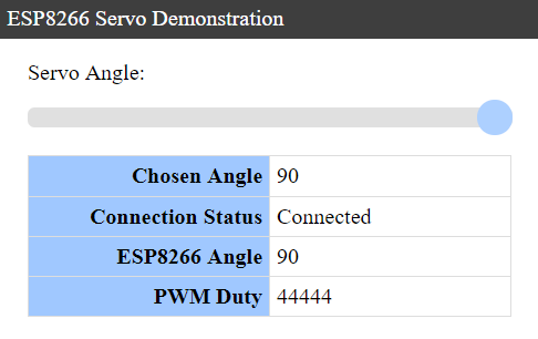
This example has a single HTML page that shows the current servo setting, and provides a slider control that the user changes to make the servo move. The servo will change position as the user moves the slider, allowing for an interactive experience.
To send the user’s choice of servo angle to the ESP8266, the web page opens a web socket connection. Web sockets are a relatively recent innovation in the world of the web, but it is a re-implementation of an idea that is almost as old as the internet itself. A web socket is a separate connection that is established by the client to the web server, over the same ports (80/443). This connection starts out looking like HTTP, with text headers that request an upgrade to a web socket connection.
Once upgraded, the web socket connection allows for arbitrary (binary and/or text) data to be sent by either the client or server at any time. This makes web sockets perfect for rapid, unsolicited updates between the user and the server, where a page refresh is not necessary.
The example program uses a web socket connection to send through the chosen servo angle as the user changes it. This is sent simply as a number string like “-83”. The ESP8266 will set the PWM signal to make the servo move to the appropriate angle and return a JSON formatted string containing the angle (for feedback) and the duty value that is used for the PWM signal.
Web sockets using libesphttpd
To accept web socket connections, the URL for the connection needs to be added to the built in URL list that is passed to the web server. The example program uses the following URLs:
1
2
3
4
5
6
HttpdBuiltInUrl builtInUrls[]={
	{"/", cgiRedirect, "/servo.html"},
	{"/ws.cgi", cgiWebsocket, ws_connected},
	{"*", cgiEspFsHook, NULL},
	{NULL, NULL, NULL}
};
This defines two URLs directly, / and /ws.cgi. The / URL uses the cgiRedirect function (built in to libesphttpd) to issue a redirection request to the client, which points them towards the /servo.html URL. If you look closely, you may notice that servo.html isn’t referenced in the above array, so how does libesphttpd know how to find it? The clue is in the second last entry, where the URL has a "*" in it, this is the catch-all URL for any unmatched URLs so far, which uses the cgiEspFsHook function. This function is also built into libesphttpd, and searches through the files that have been loaded into the ESP8266’s flash memory (from the html directory in the project) for a matching file name. In this case, the file servo.html does exist, and will be served directly from there. If no matching file exists, then it will return an HTTP 404 not found error.
For web socket connections, the /ws.cgi URL uses the cgiWebsocket function (also built in to libesphttpd) to handle the connection, with the result then passed to our own defined ws_connected function, shown here:
1
2
3
void ws_connected(Websock *ws) {
	ws->recvCb=ws_recv;
}
The function doesn’t do much of note, except to add the ws_recv function as a call-back for when a message is received over the web socket. Our example program uses this function to decode the incoming message and set the PWM duty:
1
2
3
4
5
6
7
8
9
10
11
12
13
14
15
16
17
18
19
20
21
22
23
24
void ws_recv(Websock *ws, char *data, int len, int flags) {
	if ((data != NULL) && (len > 0)) {
		// Get the desired angle from the web socket's data.
		int32_t angle = 0;
		int32_t multiplier = 1;
		for (int ii = 0; ii < len; ii++) {
			if ((ii == 0) && (data[ii] == '-')) {
				// We have a negative number.
				multiplier = -1;
			} else if ((data[ii] >= '0') && (data[ii] <= '9')) {
				// We have a numeric digit.
				angle *= 10;
				angle += data[ii] - '0';
			} else {
				// We no longer have an angle.
				break;
			}
		}
		angle *= multiplier;

		// Set the angle.
		set_servo((int8_t)angle);
	}
}
The set_servo function calculates and sets the correct duty to get the PWM high time between 1ms and 2ms:
1
2
3
4
5
6
7
8
9
10
11
12
13
14
15
16
17
18
19
20
21
22
23
24
25
26
27
28
29
30
LOCAL void ICACHE_FLASH_ATTR set_servo(int8_t position) {
	// Ensure the position is in the range of [-90 90] degrees.
	if (position < -90) {
		position = -90;
	} else if (position > 90) {
		position = 90;
	}
	servo_angle = position;

	// Calculate the duty cycle to keep it between 1ms (-90 degs) and 2ms (+90 degs).
	pwm_duty = ((uint32_t)(position + 90) * (PWM_MAX - PWM_MIN) / 180) + PWM_MIN;

	// Set the new PWM duty cycle.
	pwm_set_duty(pwm_duty, 0);
	pwm_start();

	// Send the information to all web socket listeners.
	string_builder *sb = create_string_builder(128);
	if (sb == NULL) {
		os_printf("Unable to create string builder for web socket reply.");
	} else {
		append_string_builder(sb, "{\"angle\": ");
		append_int32_string_builder(sb, servo_angle);
		append_string_builder(sb, ", \"duty\": ");
		append_int32_string_builder(sb, pwm_duty);
		append_string_builder(sb, "}");
		cgiWebsockBroadcast("/ws.cgi", sb->buf, sb->len, WEBSOCK_FLAG_NONE);
		free_string_builder(sb);
	}
}
The calculation in the code for setting the pwm_duty uses the following formula:
\[ \mathsf{pwm\_duty} = \frac{(\mathsf{angle} + 90) * (\mathsf{PWM\_MAX} - \mathsf{PWM\_MIN})}{180} + \mathsf{PWM\_MIN} \]
Where the values PWM_MAX and PWM_MIN are constants for 44,444 and 22,222 respectively.
Results
In my tests, the example program is correctly receiving the web socket information, and changing the PWM value between 1ms and 2ms as desired. Below is the plot for a 1ms output when the value is set to -90°:

At the neutral, or 0° angle, the pulse is 1.5ms wide:

And at +90°, the width of the pulse is 2ms:

Finally, a picture showing the repetition of the PWM signal:

Source
The full source code for the servo demonstration project is available in GitHub here.