This is the first in a series of blog posts to come about my adventures with the ESP8266 microcontroller. I am writing these posts as I experiment and learn about the ESP8266, so I guess this could also have been called “a beginner’s journey” or “blind leading the blind”.
About the ESP8266
The ESP8266 is a microcontroller from a company called Espressif which has built-in WiFi capabilities. While there are many other solutions that fit the above description, the ESP8266 has become one of, if not the most popular WiFi microcontrollers for DIY/hobbyist projects. Why, I hear you ask? Because they can be purchased for less than $3 in single unit quantities.
A microcontroller is like a CPU inside your computer in that it runs programs, but there are some major differences:
- Require few, if any, external electronic components to run
- Use a lot less power
- Run a lot slower
- Provides easy and direct access to inputs/output pins for connecting to other electronic components
- Either does not run an operating system at all, or runs a very minimal one
Unlike the popular AVR line of microcontrollers (which run the original Arduino boards) the ESP8266 chip itself needs more circuitry around it to be able to operate - most significantly a flash chip to hold the code to be run on the ESP8266. To make life easier, the ESP8266 is usually supplied on some sort of module, with everything you need built-in. The module that I am currently using is called an “ESP-12”. It contains the ESP8266, flash memory (typically 4MB) and a built-in WiFi antenna. The ESP-12 module exposes the most GPIO (General Purpose Input/Output) pins for use in your own projects, and is very small.
Unfortunately, one of the reasons that the ESP-12 is so small is that its connections are 2mm apart - instead of the normal 2.54 used in DIP chips and on breadboards. This means that an adapter is required to plug it into a breadboard. To avoid this problem, you can purchase an ESP8266 in a different form. Both the Adafruit HUZZAH and NodeMCU boards are breadboard friendly and look to be a great introductory setup for first-time ESP8266 usage, but I have not yet tried either.
Writing software for the ESP8266
Note: My PC at home runs Linux Mint, so all examples and instructions here will be based on using Linux. If you are running some other operating system, and want to follow the instructions here, I recommend you try running Linux in a virtual machine under Virtual Box, which is free and available for all major operating systems.
Software for the ESP8266 can be written in one of several languages:
- C / C++
- Arduino (C++ with some specialised libraries)
- Lua
- Basic
- MicroPython
There are pros and cons for each language - if you’re unsure and are new to programming in general, I’d suggest you start with either Arduino or Lua. I am going to be exploring the ESP8266 using the C language, and the open source GCC compiler. A version of the Software Development Kit (SDK) for writing C programs for the ESP8266 on Linux is available from pfalcon’s GitHub repository. This is the version that I installed, and suggest you do so to if you want to follow along here.
Once the SDK is installed, you can write your code, compile it with GCC and write it to the ESP8266 with espflashtool.py - simple, right? Fortunately, there is a tool called “make” that allows you to automate all of the above (except for writing the code). You simply need a “make file” which tells the make tool how what you want and how to do it, and make can then do the rest.
In this introductory post, I will introduce a simple program with a make file, which will let you prove that you have everything working. For the first usage of any new language on a normal PC, the first program is usually one that prints “Hello, World!”. For microcontrollers, the equivalent is to blink an LED.
The first thing to do is to write the C code. For ESP8266 programming, the main entry point to your code goes in a file called “user_main.c”
1
2
3
4
5
6
7
8
9
10
11
12
13
14
15
16
17
18
19
20
21
22
23
24
25
26
27
28
29
30
31
32
33
34
35
36
37
38
39
/*
 * user_main.c: Main entry-point for blinking an LED.
 */
#include "ets_sys.h"
#include "osapi.h"
#include "gpio.h"
#include "os_type.h"
#include "include/espmissingincludes.h"

// Timer used to determine when the LED is to be turned on/off.
LOCAL os_timer_t blink_timer;

// The current state of the LED's output.
LOCAL uint8_t led_state = 0;

/*
 * Call-back for when the blink timer expires. This simply toggles the GPIO 4 state.
 */
LOCAL void ICACHE_FLASH_ATTR blink_cb(void *arg) {
    led_state = !led_state;
    GPIO_OUTPUT_SET(4, led_state);
}

/*
 * Entry point for the program. Sets up the microcontroller for use.
 */
void user_init(void) {
    // Initialise all GPIOs.
    gpio_init();

    // GPIO 4 is an output, start with it low.
    PIN_FUNC_SELECT(PERIPHS_IO_MUX_GPIO4_U, FUNC_GPIO4);
    gpio_output_set(0, BIT4, BIT4, 0);

    // Start a timer for the flashing of the LED on GPIO 4, every 1 second, continuous.
    os_timer_disarm(&blink_timer);
    os_timer_setfn(&blink_timer, (os_timer_func_t *)blink_cb, (void *)0);
    os_timer_arm(&blink_timer, 1000, 1);
}
The make file that I use to build and flash the above code is placed in a file imaginatively called “Makefile”:
1
2
3
4
5
6
7
8
9
10
11
12
13
14
15
16
17
18
19
20
21
22
23
24
25
26
27
28
29
30
PROJ_NAME=blink
COMPORT=/dev/ttyUSB0
OBJS=user_main.o
CC=xtensa-lx106-elf-gcc
ESPTOOL=esptool.py
ESP8266_SDK_ROOT=/home/itmarshall/ESP8266/esp-open-sdk/sdk
CCFLAGS= -Wimplicit-function-declaration -fno-inline-functions -mlongcalls -mtext-section-literals \
         -mno-serialize-volatile -I$(ESP8266_SDK_ROOT)/include -I. -D__ETS__ -DICACHE_FLASH -DXTENSA -DUSE_US_TIMER
LDFLAGS=-nostdlib \
        -L$(ESP8266_SDK_ROOT)/lib -L$(ESP8266_SDK_ROOT)/ld -T$(ESP8266_SDK_ROOT)/ld/eagle.app.v6.ld \
        -Wl,--no-check-sections -u call_user_start -Wl,-static -Wl,--start-group \
        -lc -lgcc -lhal -lphy -lpp -lnet80211 -llwip -lwpa -lmain -ljson -lupgrade -lssl \
        -lpwm -lsmartconfig -Wl,--end-group

all: $(PROJ_NAME)_0x00000.bin

$(PROJ_NAME).out: $(OBJS)
	$(CC) -o $(PROJ_NAME).out $(LDFLAGS) $(OBJS)

$(PROJ_NAME)_0x00000.bin: $(PROJ_NAME).out
	$(ESPTOOL) elf2image --output ${PROJ_NAME}- $^

.c.o:
	$(CC) $(CCFLAGS) -c $<

clean:
	rm -f $(PROJ_NAME).out *.o *.bin

flash: all
	esptool.py --baud 230400 write_flash 0x00000 $(PROJ_NAME)-0x00000.bin 0x40000 $(PROJ_NAME)-0x40000.bin
Note: Be sure to change the “ESP8266_SDK_ROOT” directory above to your installation location!
Two more files are needed to make things work, but you don’t have to write either of them. The first is a file, called “user_config.h”. This is required by the SDK’s headers, but can be empty here. The second file needs to be placed in a “include” subdirectory, and is called espmissingincludes.h”. This seems to be required to fill in some procedure definitions that are not in the SDK’s headers. You can get the file from here.
Flashing your code to the ESP8266
To flash the above code to the ESP8266 is simple, simply connect the ESP8266, and run “make flash”. But how to connect your ESP8266? If you have one of the NodeMCU boards, simply plug it in to a USB port, and you’re done. The HUZZAH board needs to be connected via a FTDI USB-UART adapter, also quite easy. But if you have an ESP-12, like me? Sadly, life isn’t quite so simple.
To test out the ESP8266, I purchased a breadboard adapter for it (similar to [this one] [adapter]), which fit the breadboard’s 2.54mm spacing, but was sadly too wide to actually fit in my breadboard and let me plug wires in. But it worked with two breadboards jammed next to each other, so I went with that.
One thing to look out for is that the ESP8266 will only work with voltages up to 3.3V. If you drive any pin to 5V, you will likely break your ESP8266 permanently! Be careful, many FTDI USB-Serial adapters will output a 5V signal, which you must drop to 3.3V to avoid damage. This can be applied by a resister divider of 10KΩ from VCC to the Rx pin of the ESP8266 and the Tx line from the FTDI connector, then a 22KΩ resister to GND.
The following connections were made for an ESP-12:
| Pin | Name | Connection |
|---|---|---|
| 1 | RESET | 10KΩ - VCC, reset switch GND |
| 3 | CH-PD | 10KΩ - VCC |
| 8 | VCC | VCC |
| 9 | GND | GND |
| 10 | GPIO 15 | 10KΩ - GND |
| 11 | GPIO 2 | 10KΩ - VCC |
| 11 | GPIO 0 | 10KΩ - VCC, flash switch GND |
| 14 | GPIO 4 | 470Ω - LED - GND |
| 15 | Tx | FTDI Rx |
| 16 | Rx | FTDI Tx |
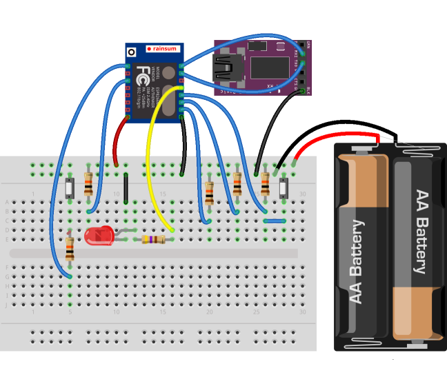
Once all this is done, hold down the flash switch and either press the reset switch, or turn the power on (or off and on if it is already on), then run the “make flash” command.
If all worked correctly, the LED should now start flashing on and off, for one second each. If so, it worked! Feel free to modify the code to see if you can change the timing - try ½ a second flashing, or on for one second, off for two.
OK, this post got a bit longer than I was expecting, so well done for anyone who managed to make it through it all! There will be more to come later, as I continue my experiments with the ESP8266.